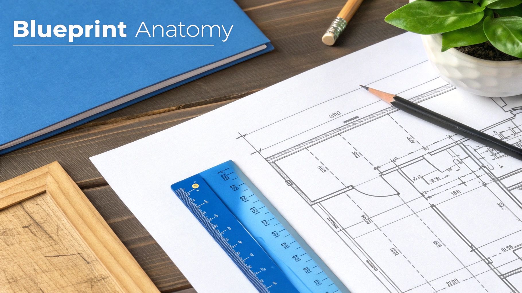
How to Read Manufacturing Blueprints Like a Pro

Reading a manufacturing blueprint is like learning a new language. It’s the language of production, and once you’re fluent, you can look at a flat piece of paper and see a three-dimensional object in your mind. It’s all about decoding the views, dimensions, symbols, and notes to bring a design to life. The process itself isn't complicated: you start with the title block to get your bearings, use the different views to build that mental model, and then dig into the details—dimensions, tolerances, and notes—for the exact instructions.
Why Blueprint Reading Is a Critical Skill

Before we get into the nitty-gritty of lines and symbols, let’s talk about why this document is the most important thing on any shop floor. A blueprint is the universal language that connects everyone—designers, fabricators, and the client. It’s the single source of truth that ensures we're all working from the same playbook, eliminating the dangerous guesswork that leads to big problems.
Getting it right from the get-go saves a ton of headaches. It prevents costly mistakes, cuts down on material waste, and makes sure the final product is precisely what the customer wanted. This isn't just a technical skill; it's the bedrock of quality, efficiency, and frankly, profitability in any custom manufacturing or woodworking business.
The Real-World Cost of Misinterpretation
Let's put this in perspective. Imagine you're building a set of custom cabinets. The blueprint calls for a tolerance of ±0.5mm on the drawer boxes, but you miss it. You build them just a hair too wide. The error is tiny, but the fallout is huge.
Now, the entire unit has to be remade. This isn't just a small hiccup; it's a cascade of problems:
- Wasted Materials: That beautiful, high-quality lumber and expensive hardware? It's now scrap.
- Lost Labor Hours: All the time your team spent on the first build is gone, and you can't get it back.
- Project Delays: The client's installation schedule gets pushed, which can seriously damage your reputation.
- Financial Loss: Your profit margin on the job just got wiped out by the cost of the do-over.
This isn't some made-up story. It happens all the time, and it shows how one small oversight on paper can snowball into a major financial and reputational disaster. Learning to read blueprints correctly is your first and best defense against these preventable nightmares. As our team at TimberCloud has seen time and again, precision in the planning stage is what truly determines success on the shop floor. You can learn more about how we're working to close that gap between design and production by exploring our mission and values.
A blueprint is more than a drawing; it's a contract. It defines expectations, specifies quality, and holds every person in the production chain accountable to the same high standard.
The Global Language of Production
As supply chains stretch across the globe, the ability to read standardized drawings is more crucial than ever. With nearly $15.8 trillion in global trade of manufactured goods recorded in 2024, blueprints are what allow a component designed in Germany to be flawlessly produced in Vietnam. It's the skill that holds international quality control together. You can dive deeper into these trends in the latest global manufacturing report.
Decoding the Anatomy of a Blueprint
Learning to read a manufacturing blueprint is less about memorizing a puzzle and more about learning a new language. Every line, symbol, and number tells you something specific. Once you know what each element means, you can start putting them together to see the full picture the designer intended.
The best way to start is by getting your bearings. Before you even think about cutting material, you need to understand the blueprint's core context. This simple first check is your best defense against common mistakes, like working from an old version of a plan.
Start with the Title Block
Your command center for any print is the title block. You'll almost always find it in the bottom-right corner of the drawing, and it's packed with the most critical, high-level information about the job. Make it a habit to look here first.
Here’s a quick rundown of what you’ll find inside:
- Part Name and Number: The official identifier for the component.
- Material Specifications: Tells you exactly what the part is made of (e.g., 6061-T6 Aluminum or 304 Stainless Steel).
- Revision History: This is a big one. It shows if you're working from the latest version, preventing you from making an obsolete part. Always check the revision letter or number.
- Tolerances: General tolerances that apply to any dimension without a specific tolerance listed next to it.
- Scale: The ratio of the drawing to the real-world part (e.g., 1:2 means the drawing is half the size of the actual object).
- Company Information: Who designed it and who drew it.
Skipping the title block is a classic rookie mistake. A thirty-second scan can save you from grabbing the wrong material or, even worse, building a part from a design that was scrapped two weeks ago.
The Language of Lines
With the basics covered, the next step is to understand the alphabet of the drawing: the lines themselves. Different line types communicate different things, and mixing them up can lead to some serious fabrication errors. A solid line means one thing, a dashed line means something else entirely.
For example, think about a simple custom cabinet door you're building.
- Object Lines: These are the thick, solid lines that outline the door's visible edges. They define its height, width, and overall shape.
- Hidden Lines: Dashed lines are used to show features you can't see from that angle, like the location of internal dowel pins or the depth of a mortise on the back side.
- Center Lines: You'll see these as a long-dash, short-dash pattern. They mark the exact center of a feature, like where to drill the hole for a knob.
A blueprint serves as the universal communication language within a manufacturing organization. It bridges critical gaps between design, engineering, production, and even the customer, ensuring everyone operates from the same technical specifications. You can learn more about how standardized drawings reduce manufacturing delays on catalystconnection.org.
Lines are the building blocks of any drawing. To help you get familiar with them, here's a quick guide to the most common ones you'll encounter.
Essential Blueprint Line Types and Their Meanings
| Line Type | Appearance | Purpose in the Blueprint |
|---|---|---|
| Object Line | A thick, solid, continuous line | Defines the main, visible outline and edges of the part. |
| Hidden Line | A medium-weight, dashed line | Shows edges or features that are not visible from the current view. |
| Center Line | A thin line with alternating long and short dashes | Marks the center of holes, arcs, and symmetrical features. |
| Dimension Line | A thin, solid line with arrowheads at each end | Indicates the distance between two points, with the measurement in the middle. |
| Extension Line | A thin, solid line extending from the object | Used with dimension lines to show exactly where a measurement begins and ends. |
Getting comfortable with these lines will make interpreting the rest of the drawing much faster.
Visualizing the Part with Different Views
Now we can put those lines into context by looking at the different views. Because you can't easily show a 3D object on a 2D piece of paper, blueprints use a system called orthographic projection. This just means you get a few different 2D views of the part—typically a front, top, and side view.
Each view shows the part as if you're looking at it straight-on from that one direction.
Let’s go back to that cabinet door. The front view would show its height and width. The top view would just look like a thin rectangle, showing you the door's thickness. The side view would look identical to the top view in this simple case, also showing the thickness. By mentally stacking these views together, you build a complete 3D picture in your head.
Often, you'll also see an isometric view tucked into a corner of the blueprint. This is a 3D-style sketch of the finished part. While it's not used for taking measurements, it’s incredibly useful for double-checking your interpretation of the 2D views. It helps confirm you've got the right picture in your head before you start making cuts.
Mastering Dimensions and Tolerances
If the lines and views on a blueprint are the skeleton, then dimensions and tolerances are its heart and soul. These are the numbers that define precision, dictating the exact size, shape, and fit of every feature. Getting this right is non-negotiable—it's what separates a perfect component from a piece of scrap.
It’s easy to glance at a print and see a number like ‘50mm,’ but that’s only half the story. The real secret is in the tolerance, which defines the acceptable amount of variation for that dimension. Since no manufacturing process is absolutely perfect, tolerances tell you just how close to perfect you need to be.
Why a Number Is Never Just a Number
Let's say you're machining a simple pin that needs to fit snugly into a hole. The blueprint calls for a 50mm diameter, but right next to it, you see ±0.1mm. That little note changes everything.
Suddenly, the instruction isn't "make this exactly 50mm." Instead, it's "make this anywhere between 49.9mm and 50.1mm." This acceptable wiggle room is what makes modern manufacturing work. It ensures that any pin you make will fit correctly into any corresponding hole, a concept we call interchangeability.
Tolerance isn't about being sloppy; it's about defining an acceptable, repeatable level of precision. Tighter tolerances often mean higher costs and more complex manufacturing processes, so they are only used where absolutely necessary for the part's function.
This skill is more critical than ever. The 2025 manufacturing outlook shows US manufacturers are battling higher costs, making operational efficiency—driven by accurate print reading—a must-have for staying profitable. With global trade of manufactured goods hitting nearly $15.8 trillion in 2024, blueprints are the universal language that keeps international supply chains moving. You can read the full analysis on this from the National Institute of Standards and Technology.
Understanding Different Types of Tolerances
You’ll see tolerances written in a few different ways, and it’s important to spot the difference right away. They usually fall into two main categories.
-
Bilateral Tolerance: This is the common "plus-or-minus" format we just talked about (±0.1mm). It’s symmetrical, meaning the dimension can vary in either direction (larger or smaller) from the target size.
-
Unilateral Tolerance: This type allows variation in only one direction. It might look like 50mm +0.2/-0.0. In this case, the part can be up to 50.2mm but can not be smaller than 50.0mm. You’ll see this often where a specific type of fit is needed, like a press-fit where the pin has to be slightly larger than the hole.
Recognizing these subtle differences is the key to getting the part's function right. Bilateral gives you flexibility; unilateral sets a hard limit in one direction.
A Glimpse into GD&T
Once you get comfortable with basic dimensions, you’ll start running into Geometric Dimensioning and Tolerancing (GD&T). Think of it as an advanced symbolic language that controls not just the size of features, but also their form, orientation, and location relative to each other.
For example, instead of just controlling a hole's diameter, GD&T symbols can specify its straightness, its perpendicularity to a surface, or its exact position. A full dive into GD&T is a course in itself, but just being able to recognize the symbols is a huge first step. When you see boxes on a print with symbols like ⌖, ⟂, or ○, you know they contain critical instructions about the part’s geometry that go way beyond simple measurements.
This is where modern software really shines. Platforms with plan-to-production engines can interpret these complex GD&T requirements to generate production-ready orders automatically. To see how this works in practice, you can explore the features available on TimberCloud.
Don't Forget the Drawing Scale
One last piece of the puzzle is the drawing scale, usually found down in the title block. This tells you how the size of the drawing on the page relates to the actual, physical size of the part. Never, ever assume a drawing is a 1:1 representation.
Here’s a quick rundown of what you’ll see:
- 1:1 (Full Scale): What you see is what you get. The drawing is the same size as the final part.
- 1:2 (Half Scale): The drawing is half the size of the part. One inch on the print equals two inches on the real thing.
- 2:1 (Double Scale): The drawing is twice the size of the part. This is common for small, intricate components where you need to see the details blown up.
The scale is your reality check. It helps you visualize the true size of what you're about to build and keeps you from being tricked by the drawing itself. Always check the scale before you start measuring.
Interpreting Symbols and Notes
While the views and dimensions give you the basic shape and size of a part, the symbols and notes are where the real manufacturing secrets lie. This is where the blueprint tells you how to build something, not just what it looks like. Think of this section as the decoder ring for all those finer details that separate a good part from a truly great one.
Ignoring these elements is one of the fastest ways to derail a project. A tiny symbol can dictate the strength of a critical joint, and a single note can completely change the look and feel of a finished piece. For any fabricator who cares about quality, learning to speak this specialized language is non-negotiable.
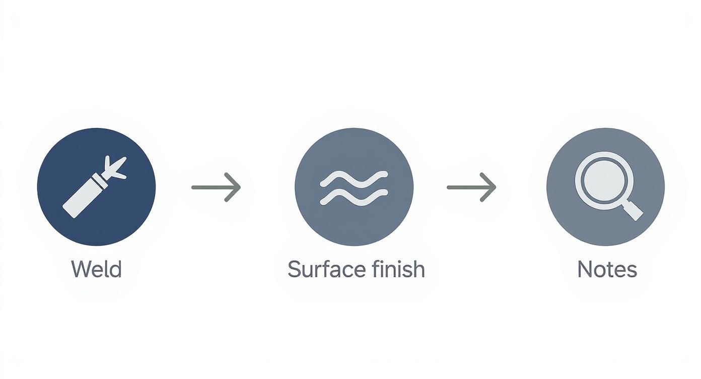
Cracking the Code of Common Symbols
Symbols are the shorthand of manufacturing. They’re standardized icons that get complex instructions across quickly, no matter who is reading the print. While you’ll encounter hundreds of them over a career, a few key categories show up on almost every custom manufacturing or woodworking drawing.
These are the ones you absolutely have to know:
-
Weld Symbols: These tell a welder everything required to join two pieces of metal. A simple arrow points to the joint, while the symbols on the line specify the weld type (like a triangular fillet weld or a butt weld), its size, and whether it’s on the "arrow side" or "other side" of the joint. Get this wrong, and you could compromise the structural integrity of the entire build.
-
Surface Finish Symbols: This little icon, which usually looks like a checkmark with a number, dictates the required texture or smoothness of a surface. A number like Ra 3.2 (which stands for Roughness Average in micrometers) tells a machinist exactly how smooth that face needs to be. A lower number means a smoother, more precise—and often more expensive—finish, which is absolutely critical for parts that need to seal, slide, or fit together without a hair's breadth of slop.
-
Thread Notations: For any part that gets a screw or bolt, you’ll see thread callouts. A notation like M10 x 1.5 - 6H is packed with information: it's a metric thread (M), has a 10mm nominal diameter, a 1.5mm pitch (the distance between each thread), and a specific tolerance class (6H) for the internal thread. Grabbing the wrong tap for that hole will render the entire part useless.
Symbols aren't just friendly suggestions; they are legally binding instructions. In a certified shop, failing to meet the spec on a symbol is the same as missing a dimensional tolerance. It results in a non-conforming part, plain and simple.
To help you get a handle on these, it's useful to see them side-by-side. Each category of symbol has its own distinct visual language.
Common Manufacturing Symbols at a Glance
| Symbol Category | Example Symbol (Visual) | What It Represents | Common Application |
|---|---|---|---|
| Welding | A fillet weld, typically used for joining two pieces at a 90-degree angle. | Fabricating metal frames, brackets, and structural supports. | |
| Surface Finish | The required smoothness of a surface, measured in micrometers (Ra). | Mating surfaces on engine blocks, bearing seats, or any part needing a tight seal. | |
| Geometric Tolerance | How perpendicular one surface must be in relation to another, within a specified tolerance zone. | Ensuring a mounting bracket is perfectly square to its base. |
This is just a starting point, of course, but recognizing the type of symbol you're looking at is the first step toward understanding the designer's full intent.
The Overlooked Goldmine: The Notes Section
If symbols are the shorthand, then the notes section is the detailed instruction manual. You'll usually find it as a block of text near the title block, and skipping it is a recipe for disaster. This is where designers put all the critical information that simply can't be communicated with lines and symbols alone.
Forgetting to read the notes is like trying to build IKEA furniture without the instructions—you might end up with something that looks like a bookcase, but it's almost certainly wrong and probably about to fall over. The notes cover everything from general shop practices to specific, one-off requirements for that particular job.
A Custom Furniture Case Study
Let's say you're building a high-end walnut credenza. The main drawings and dimensions look straightforward, so you just skim the notes section. Here’s what you might miss:
- "ALL EXTERIOR PANELS TO HAVE BOOK-MATCHED VENEER WITH CONTINUOUS GRAIN FLOW ACROSS DOORS." You ignore this and just cut your panels for maximum yield. The result? A disjointed, chaotic grain pattern that looks cheap. The client takes one look and rejects the piece.
- "BREAK ALL SHARP EDGES TO 0.5MM RADIUS UNLESS OTHERWISE SPECIFIED." You deliver the credenza with crisp, knife-sharp edges. While it's built to dimension, it feels unfinished and is prone to chipping. That tiny detail was the difference between a bespoke piece and a factory reject.
- "FINISH: POST-CATALYZED CONVERSION VARNISH, 30 SHEEN." You just use the standard lacquer you have in the shop. The sheen is wrong, and more importantly, the durability is far lower than what the designer specified for a high-traffic piece of furniture.
In this one project, skipping a few sentences in the notes has completely tanked the aesthetics, feel, and function. This is why seasoned pros read every single word on a blueprint before a tool ever touches the material. The real story of how to read manufacturing blueprints is often found in the text, not just the drawings.
A Practical Blueprint Walkthrough
Theory is great, but getting your hands dirty is where the real learning happens. Let's put the concepts into practice and walk through a manufacturing blueprint for a custom shelving unit. This is how you'll connect the dots and see how abstract rules turn into actionable steps on the shop floor.
We'll approach this just like a seasoned fabricator would. First, we'll hit the title block to get the lay of the land. Then, we’ll use the orthographic views to build a 3D picture in our minds.
First Look: The Title Block and Views
Let's say the blueprint in front of us is for a single steel support bracket. The very first place I look is the title block. It's the project's ID card. Here, I'd confirm the part name ("Shelf Support Bracket"), see the material is A36 Steel, and note that we're on Revision B—always work from the latest version. The scale is listed as 1:2, which tells me the drawing is half the size of the real-world part.
With that baseline info, my eyes move to the orthographic views. I can see the L-shape of the bracket in the front view. The top view shows me its width and, crucially, where the mounting holes go. A quick glance at the right-side view confirms the material thickness. By piecing these three flat drawings together in my head, I've got a solid three-dimensional model of the bracket.
Examining a Critical Component
Now, let's zoom in on a specific feature—one of the mounting holes in the top view. The dimension line points to it, calling out a diameter of 12.5mm. But the real story is in the tolerance: ±0.1mm. This is a direct instruction. The hole can't be any smaller than 12.4mm or larger than 12.6mm. That tight a window ensures the M12 mounting bolt fits perfectly, with no wiggle room.
Right next to it, another callout points to the surface that will sit against the wall. A surface finish symbol shows a value of Ra 6.3. This tells the machinist that the surface needs a moderately smooth finish, probably done with a grinder, to ensure a flat, stable mount. It's a perfect example of how blueprints communicate not just size, but texture and function.
A blueprint isn't just a picture; it's a complete set of instructions. Every dimension, symbol, and note is a direct command from the designer to the fabricator, with each detail serving a specific purpose in the final assembly.
Interpreting Key Symbols and Notes
Okay, let's hunt for symbols. These are the graphical shortcuts that save a ton of space and prevent ambiguity. Reading them correctly is non-negotiable.
You have to know what you're looking for, from how parts are joined to how they're finished.
This kind of visual guide is handy for quickly identifying common manufacturing symbols, each of which is a specific command for the person making the part.
Let's find a few on our bracket blueprint:
-
Counterbore Symbol: One of the mounting holes has a symbol that looks like a flat-bottomed 'U' next to it. That's a counterbore. The note "⌴ DIA 20mm ↧ 5mm" is the instruction: drill a larger, flat-bottomed hole 20mm wide and 5mm deep. This lets the head of a socket-head cap screw sit perfectly flush with the bracket's surface.
-
Weld Symbol: At the inside corner of the L-shape, an arrow points to the joint, and a small triangle sits above the line. That's a fillet weld symbol. The "6" next to it calls for a 6mm weld, giving the bracket the strength it needs to handle a heavy load without failing.
Finally, a quick scan of the general notes section reveals Note #3: "DEBURR ALL EDGES." This might seem minor, but it's a critical step for safety and a professional finish. No one wants to handle a part with razor-sharp metal shards left over from machining.
This process—moving from the big picture down to the finest detail—is how you build the confidence to tackle any job. For more tips and manufacturing insights, check out the articles over on the TimberCloud blog.
Got Questions? Let's Talk Shop Floor Realities
Knowing the basics of blueprint reading is one thing, but the real learning happens on the shop floor. That's where the "what ifs" and unexpected problems pop up. Let's walk through some of the most common snags you'll hit when you start working with these prints day in and day out.
Think of these as the real-world scenarios that can bring a project to a screeching halt if you're not prepared. Tackling them head-on is how you go from just reading a print to truly understanding it.
What If I Find a Conflicting Dimension?
This is a classic, and I guarantee you'll run into it. You're looking at a print, and the front view clearly marks a feature as 150mm. But then you glance at the top view, and the same feature is labeled 150.5mm. So... which is it?
The number one rule here is simple: never guess. Stop what you're doing right now. The time it takes to ask a question is nothing compared to the cost of scrapping a part made from a bad assumption. First, check the title block and make sure you have the most current version of the print. If you do, your next move is to flag it for the engineer or designer who drew it up.
A conflicting dimension on a blueprint isn't a puzzle to solve—it's a stop sign. Before you cut a single piece of material, that ambiguity has to be resolved by the person who created the drawing.
Make sure you document the issue, too. It protects you, the project, and ensures the final, corrected dimension is on record for everyone to see.
How Do I Handle a Missing Dimension?
Just like a conflict, a missing dimension is a full stop. If you can't find a critical measurement for where to place a hole or how deep to make a cut, you can't just wing it. Don't even think about trying to measure it off the paper with a scale ruler; prints are rarely drawn perfectly to scale, and you're just asking for trouble.
The process is the same as with a conflict: halt all work on that specific feature and send a formal request for the information. It's the design team's job to give you a complete road map. Trying to fill in the blanks yourself means you're taking on the liability if that part comes out wrong.
Why Revision Control Is a Big Deal
Blueprints aren't set in stone. They evolve. Designs get tweaked to fix a small error, improve the part's function, or make it cheaper to manufacture. This is all tracked with revision control—that little letter or number in the title block, like Rev A, Rev B, or Rev 1.2.
- Always Check First: Before you even think about starting a job, confirm you have the latest revision. Make it a habit.
- Read the Notes: Look for a change log table, usually near the title block. It'll tell you exactly what's different. You might see a note like, "Rev B: Changed hole diameter from 10mm to 12mm."
- Destroy Old Prints: When a new revision comes out, get the old one off the shop floor immediately. A part made from an old print is 100% scrap, no exceptions.
Following revision control is the bedrock of good quality control. It’s a simple check that prevents massive, costly headaches down the line and is one of the most critical habits for anyone serious about mastering blueprints.
At TimberCloud, Inc., we're building tools to bridge the gap between your designs and your production floor, cutting down on the human error that comes from interpreting complex prints. Our platform can analyze your blueprints to generate production-ready orders in minutes, making sure every last detail is captured accurately. See how we can simplify your workflow at https://timbercloud.com.
Topics
TimberCloud Team
Content Team
The TimberCloud team is dedicated to helping manufacturers streamline their operations with intelligent software solutions.